- AustraliaEnglish
- BelgiumDutchFrench
- BrasilPortuguese
- CanadaEnglish
- Greater ChinaSimplified ChineseTraditional Chinese
- FranceFrench
- GermanyGerman
- GlobalEnglishFrenchSpanish
- GreeceGreek
- IndiaEnglish
- ItalyItalian
- JapanJapanese
- LuxembourgFrench
- MexicoSpanish
- Middle East & AfricaEnglish
- NetherlandsDutch
- PolandPolish
- PortugalPortuguese
- SpainSpanish
- South AmericaSpanish
- SwedenSwedish
- TurkeyEnglish
- United KingdomEnglish
- United States of AmericaEnglish
Inverters: power electronics for a clean power supply
This article was originally published 2017 or before. The information may be outdated.
Practically all modern energy supply grids work with alternating current, and for a good reason. One can generate this simply with the help of synchronous generators. One can transmit this trouble free over long distances, since AC voltage can be very simply transformed to other levels. Additionally, electrical consumers can be simple, because they can be connected safely protected against polarity reversal. However also direct current plays as before an important role: not only street cars and battery charging devices, as good as all electronic circuits need this in order to operate. Batteries, fuel- and solar cells supply direct current exclusively. Understandably rectifiers and inverters have a large practical importance as links between both electrical systems. Rectifiers are to be found in almost all wall power supplies, however inverters are also prevalent: whether for the operation of commercial 230 V devices in cars, in uninterrupted power supplies or for the use of renewable energies - there is a huge amount of applications for inverters. The feeding in of environmentally friendly generated electricity into the utility grid has developed into a main focus of inverter technology. The inverter is the interface to the utility grid for most wind power plants [1] and all photovoltaic systems without exception - the central element of PV systems. It is not only responsible for the complete conversion of the direct current into alternating current, rather firstly ensures that the solar cells operate at the optimal working point, monitors the grid and the output of the PV system. Also the dimensions are impressive: alone in Germany there were PV inverters with over five Gigawatts of power on the grid at the end of 2008 - the tendency is for further increases.
[1] modern wind energy system work mostly with a direct current intermediate circuit, in order to feed in constant (grid) frequency despite changing revolution speeds
Distinguishing criteria
An important distinguishing feature of inverters is the form and quality of the outgoing signal, that is the temporal curve of the AC voltage. This is normally the sine function - exactly like the voltage curve that a synchronous generator generates. Also the models and equivalent networks based on complex alternating current calculations call for harmonic and therefore sinusoidal voltage curves and have proven themselves for the dimensioning of alternating current circuits. Purely mechanically operating contact inverters only generate a square-wave voltage which is best suited to the operation of simple consumers (e.g. light bulbs). Modern electronic inverters supply in contrast a clean, exact sinusoidal outgoing voltage, which can not be differentiated from that of a synchronous generator. Decisive for the quality of the inverter is also naturally the efficiency with which the current conversion takes place. The most important question is: how much of the direct current fed in comes out of the other side as alternating current? The best devices achieve here efficiencies of over 98 percent and with this lie close to the limit of physical possibility.
A further criterion regards themode of operation: Grid-tied inverters, which are used in most PV systems, adjusts themselves to the utility grid in terms of frequency and phasing. They synchronise to the grid to feed-in the PV energy. Uninterrupted power supplies and off-grid systems use so called island inverters, which stipulate the frequency and voltage themselves and therefore act as a grid former.
Chopper circuit
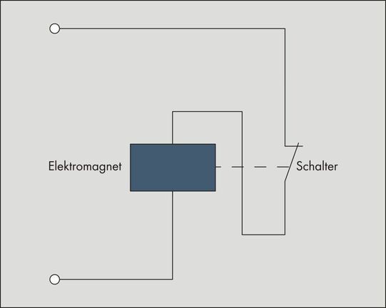
The functionality of an inverter is best clarified analogously with its technological development: beginning with the purely mechanical contact inverter and ending with modern inverters based on semiconductors. The contact inverter is based on the principle of Wagner`s Hammer - similar to the previously used break-time bells: a relay is set in oscillation, in which its excitation current interrupts itself when activated. It drops out, switches the excitation current on again as a result and the procedure begins again [Fig.1].
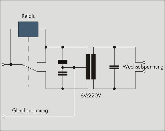
Instead of the hammer hitting the bell, the relay can also switch the polarity of the output voltage - the chopper circuit is finished [Fig. 2]. The frequency of the output voltage results from the inertia of the relay, which can be change with the help of an oscillating weight. Due to the various disadvantages such as high level wear, strong noise development as well as disturbance emissions based on contact sparks this type of inverter has not been used for a long time - completely apart from the limited usefulness of the generated square wave voltage.
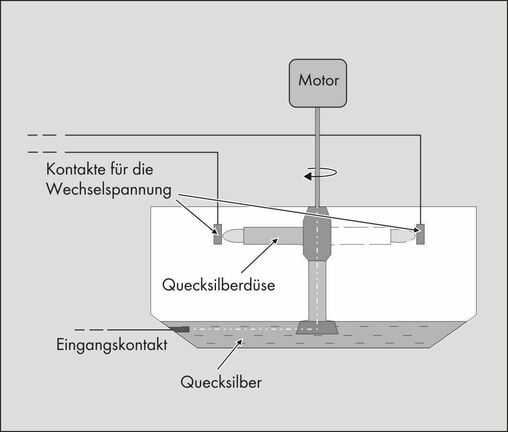
A technically interesting further development was still the so-called turbo inverter, which was used for the battery fed lighting of railroad wagons: the relay contacts were replaced here with a conductive stream of liquid mercury which rotated in a closed housing and thus coated two contact points alternatively [fig. 3].
H Bridge Circuit
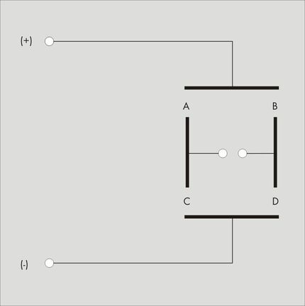
The decisive breakthrough came with the development of the semiconductor technology: power transistors as electronic switches made possible the construction of much more efficient devices - without the formation of sparks, noises or mechanical wear. The H bridge circuits used four med until today the basis of every inverter [fig. 4]: four semiconductor switches open and close alternatively in pairs crosswise, so that the polarity of the middle "bridge" swaps every time. The temporal control of the semiconductor determines the frequency of the polarity reversal and therefore the output-side inverter voltage: in the simplest case the switch statuses between "A+D open" and "B+C open" is switched 100 times per second - which gives a square wave voltage of 50 Hz.
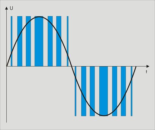
The first semiconductor inverters functioned in this way, replaced the thyristors as switch elements and quickly proved itself robust and reliable. As a result of the further development of semiconductor technology much more is possible since then. Modern power transistors have a maximum switching frequency of more than 10,000 Hz, thus can switch much more quickly than would be necessary for the output frequency of 50 Hz. One takes advantage of exactly this with pulse width modulation technology: a considerably faster synchronized bridging circuit generates many short voltage pulses [2] of various durations (pulse width), which produce the desired output signal in the time average. The pulsed voltage is able to be modulated therefore to every desired signal form - naturally also to the desired sine wave [Fig.5]. An inductor smoothes out the signal (low-pass filter) composed of short pulses - the result is a clean, sinusoidal alternating voltage. In order to achieve the necessary magnitude of voltage (230, 400 or 20,000 Volts) a transformer is normally connected downstream of the inverter bridge. This additionally ensures a galvanic separation between DC and AC grid. There are however also inverters without transformers: The devices are smaller, respectively lighter and achieve a somewhat better efficiency. The desired magnitude of voltage is in this case achieved via a boost chopper [3] which is connected upstream of the inverter bridge.
[2]Most solar inverters are voltage driven, since they feed into the electricity grid with their specified grid voltage. Here, the sinusoidal alternating voltage is correctly composed of short current impulses
[3] Electronic switching for the increase of direct voltages
Main focus: photovoltaics
As already mentioned, solar electricity generation has over the last years become the most important market for inverters. At the same time PV inverters have been significantly improved and have achieved a highly technological level. After a short description of the current PV technology, the most important requirements of a PV inverter will be explained.
Basics
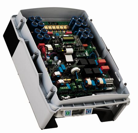
The solar cells are integrated into approx. 1.3 x 1.9 meter square modules. When exposed to solar irradiation they deliver a direct voltage which causes a direct current to flow in a connected electrical circuit and can thus be used. The inverter converts this direct current into grid conforming alternating current (e.g. 50 Hz / 230 V for the German low voltage grid) and feeds this into the utility grid against remuneration. Many countries have legal regulations for the remuneration of solar electricity, in order to promote the environmentally friendly electricity generation from sunlight. Most of these promotional measures run over 20 years, so that solar systems are designed for at least such a lifetime. There are various types of solar cells, which vary greatly in price and energy yield. Many concepts are also available in the case of inverters - depending on system size: from module inverters (output related to the individual solar module) to the classic string inverter (output 2.5 to 11 kW) right up to central inverters (output 100 - 1,200 kW) with which football field sized PV power plants are driven. They feed the energy in part directly into the medium voltage grid - with a voltage of 20,000 volts. The planning and design of a solar power system is in the process a complex subject: selection and circuitry of the modules and inverters, central or decentral system construction - there are infinite varieties. out of which the respective optimum must be found. The tasks of the inverter are numerous in every case..
DC Seperator
The speciality of solar modules is that under exposure to light they are always energized. Even a possible short-circuit does not change this, since the short-circuit and open circuit voltage of solar modules differ from one another only marginally due to the high internal resistance. Therefore one can not turn off a solar module - unless one sets it completely in darkness. If the cable is separated under load, dangerous electric arcs can occur, which as a result of the direct current do not extinguish[4]. In order to be able to work on the inverter without danger, a DC side circuit breaker is therefore prescribed: it can disconnect the inverter from the solar modules even under load. This special circuit breaker can be integrated directly into the inverter, which then clearly reduces installation and cabling complexity.
[4] With alternating current the electric arc can easily extinguish in the sinusoidal zero crossing
MPP-Tracking
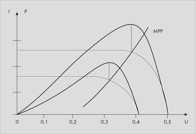
The second direct-current-side challenge is related to the current-voltage characteristic curve of the solar module. This is not constant, rather dependent on the temperature, the irradiation strength and the type of solar cells used. Stronger irradiation increases the magnitude of current whilst the voltage remains virtually the same. A greater temperature in contrast lowers the voltage whilst the strength of current remains virtually the same. The non-linearities necessitate a constant power adjustment between the inverter and the solar modules. If one multiplies the current- and voltage values of the "effective actual" characteristic curve, one has the respective power characteristic curve. This has a maximum, the so-called Maximum Power Point (MPP). It represents the respective combination of current and voltage values, at which the module currently delivers the greatest power. [fig. 7]. This inverter has the task of maintaining the solar modules at the MPP constantly, through the systematic changing of its internal resistance. This procedure is known as MPP tracking and amounts to changing the internal resistance at regular time intervals and observing the resulting power changes. In the event of a power increase the new internal resistance and therefore the new MPP voltage is taken on - otherwise the values remain unchanged.
Conversion Efficiency
The next step is about converting the solar generated direct current as completely as possible into alternating current. For this the bridge circuit must be optimally synchronized, all components (power semiconductors, coils, capacitors) must be of the highest quality and perfectly attuned to one another. The path to efficiencies of 98.X percent achieved today was relatively long - the last great step took place with the development of the so-called H5 topology by SMA. Hidden behind this is a decisive improvement of the already described, classic inverter bridge circuit (H4 topology). A fifth power semiconductor between the input capacitor and bridge inhibits a loss inducing oscillation of electrical charge and clearly lowers the power loss once again.
Temperature Management
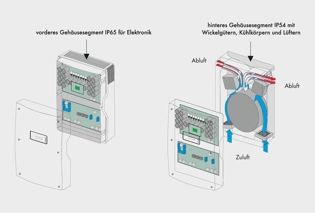
The inverter's temperature management is also important for the conversion efficiency. Since even with an efficiency of 98 percent lost heat still accumulates: with a 10 kW device this is at least 200 watts of warm power, for a central inverter with 630 kW nominal power this 2 percent of loss through warmth is a handsome 12,600 watts. If the temperature in the device innards climbs too strongly, the behavior of sensitive components change until they fail. Therefore the power of the inverter is automatically reduced and the MPP of the solar generator is lost. A generous cooling air fan would however likewise minimize the energy yield. Decisive therefore is an intelligent cooling concept, consisting of the optimum spatial layout of all components and an efficient and suitably dimensioned fan [fig. 8]. Inverters constructed so work at temperatures of up to 50 degress Celsius at nominal power - and a full energy yield.
Housing
Despite the necessary cooling PV inverters normally need a weather resistant housing (optimum: protection rating IP65), that the unprotected outer assembly allows at the desired locations. This is sensible for large open air systems, but also for the solar systems on private roofs. Since by mounting the inverter close to the modules the length of the expensive and complex DC cabling is reduced. (Due to the mostly large current strengths in the direct current circuit larger cable cross-sectional areas are here necessary in order to keep the power losses low[5].)
[5] The power loss increases quadratically with the current strength. P=RxI2
Grid monitoring
The monitoring of the utility grid into which the solar electricity is to be fed into also belongs to the tasks of the inverter. In order that nobody injures themselves whilst working on the supposedly voltage free grid, all energy sources - therefore feeding-in inverters also - must be able to be separated from the grid at all times. The German VDE standard 126.1.1. dictates exactly how the grid must be monitored (three phase voltage monitoring, frequency and impedance measuring) and how the separator should appear: doubly installed and connected in series it must separate the inverter from the grid within a few milliseconds. Incidentally, also if the measured grid parameters are above the permissible thresholds: if the grid frequency climbs too strongly due to an oversupply of power, the inverter likewise separates itself from the grid. Grid monitoring is complicated by the fact that globally varying regulations, standards and grid connection conditions are valid, which the inverter must satisfy.
Plant monitoring
Trust is good, control is better - this principle is also valid for PV systems. Although they have few moving parts and do not succumb to wear. All the same there are factors which negatively influence power of the system: For example individual solar modules can become dirty or damaged, fluctuations in voltage or frequency can lead to short term shut downs - in the worst case regularly. All these things can lead to significant yield losses, if they remain unnoticed over long periods. A continual monitoring of the system is therefore important and recommended. For this the inverter must have at least one communications interface at which all electrical parameters of the AC and DC sides (voltage, current strength, power...) are available. Mostly, however, considerably more values are recallable, right up to the isolation resistance or the number of power-ups. A network connection, an industry bus such as RS485 or in the case of the new generation SMA devices a wireless Bluetooth® interface of class 1 (range up to 100 m in open air) serve for communication. Together with the measured values from external sensors the data is called up from an additional data logger, prepared, archived and made available via a network connection. Via an existing internet connection (if necessary also by GSM) the data can be transferred to a corresponding data portal, which is recallable worldwide.
Degression
A completely different requirement of the inverter results from the market situation, more accurately from the (at least in Germany) annually sinking reimbursement rates for solar electricity. The most successful principle of the Renewable Energy Law (EEG), taken on by 47 countries up to now, envisages that operators of solar systems receive a fixed price for every kilowatt hour generated over 20 years, the value of which is dependent upon the time of commissioning. This reimbursement rate for systems newly connected to the grid sinks annually (degression of the incentive). For roof system the rate for 2009 is eight percent lower than that of 2008 - in 2010 it will sink by a similar magnitude. The sinking incentive should be accompanied by increasing units and respectively lower prices. For the inverter and all other system components this means: the prices and therefore manufacturing cost must really sink each year, in order that the installation of solar power systems continues to pay. In the previous years this was successfully achieved at least with inverters [6] - through the greatly improved device power. The degression remains however a permanent challenge to all manufacturers of solar technology components.
[6] Raw material bottle-necks caused a price increase in 2008 for solar modules.
Upcoming challenges
Alongside the politically wanted price pressure, the further increase of the efficiency belongs to the tasks which face the manufacturers of inverters. Similar to the pulse frequency of CPUs, here there was a regular increase to be observed over the last years. The 99 percent mark will thus fall in the foreseeable future. A completely new subject field has been moved onto the agenda as a result of the meanwhile completely noticeable percentage of renewable energies as a supply of power: participation in grid management. Background is the complex task of the grid regulation, which must constantly balance the power supply and power consumption - temporally as well as spatially. An increasing portion of energy in-feeders, which operate totally independently can compromise the grid safety and therefore the safety of supply. For the desired further development of renewable energies it is therefore necessary that at least the larger generation systems participate in grid management. For technical control purposes they must be integrated into the control room of the respective utility grid operator or at least allow the operators limited remote control. Respective regulations are already in place since the start of 2009, further follow in the coming months and years. Limiting of the feeding-in of effective power, support of the grid voltage through transfer of reactive power, feeding-in of short-circuit current on the event of faults - the requirements are complex. The realization of these requirements can only take place through the inverter. Their importance as "heart and brain" of every solar power system will therefore increase in the future.